DC-UPS modules – with battery or capacitor?
An uninterruptible power supply is essential in certain industries: If manufacturing processes are disrupted due to power interruptions, high costs can be incurred. There is also a risk of data loss and damaged systems. DC-UPS modules reduce this risk by bridging power outages or load fluctuations with the help of batteries or electrochemical double layer capacitors. However, in which applications which UPS type is needed depends on numerous factors.
PULS currently offers two options for continuing to supply power to the load in an emergency: both electrochemical double-layer capacitors and lead-acid batteries can serve as energy storage in DC-UPS systems for industrial plants.
Electrochemical double-layer capacitors, also known by trade names such as Ultracap, Supercap or Greencap, have been available on the market for over 25 years and have become reliable and well-tested components. Initially quite expensive, these components are suitable as energy storage devices for DC-UPS units and can be used for applications such as storing braking energy or providing short peak currents.
Lead-acid batteries have gained a strong competitor in the form of electrochemical double-layer capacitors. However, both UPS types have their benefits depending on the application. These are explained in the following comparison:
When comparing energy densities, batteries always win
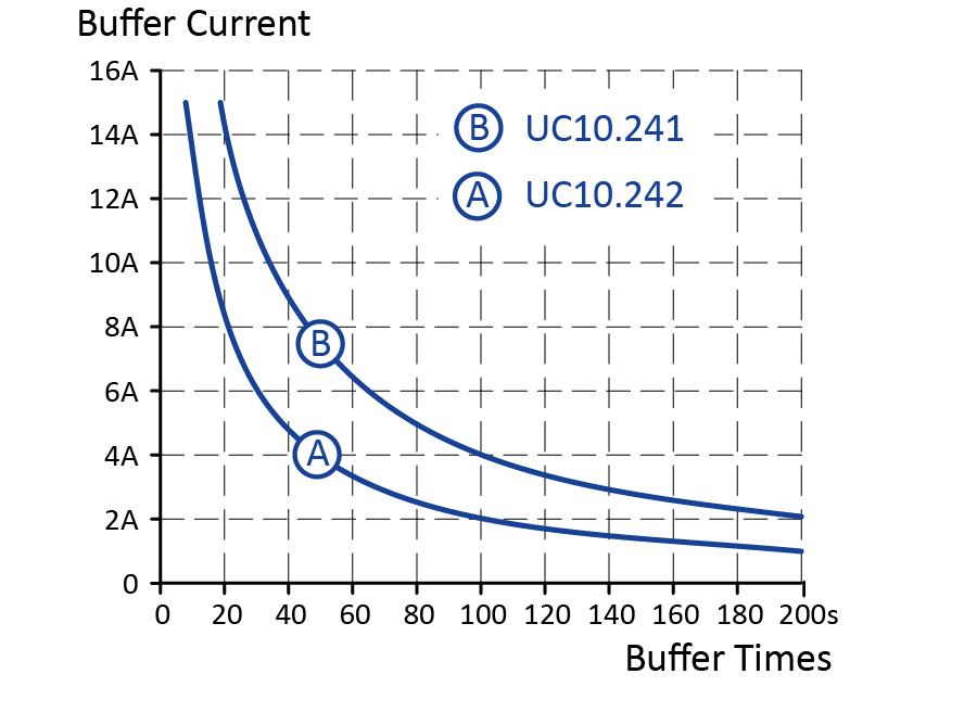
Comparing the hold-up times of capacitor-supported and battery-supported systems is not useful. Batteries always win when comparing energy densities. However, it is equally important to consider the actual hold-up time required: While UPS modules with capacitor storage buffer in the range of seconds (see graph 1), UPS modules with batteries guarantee an uninterruptible power supply of up to several hours (see graph 2).
If the actual hold-up time required is between 15 and 150 seconds, electrochemical double-layer capacitors can keep up in terms of price.
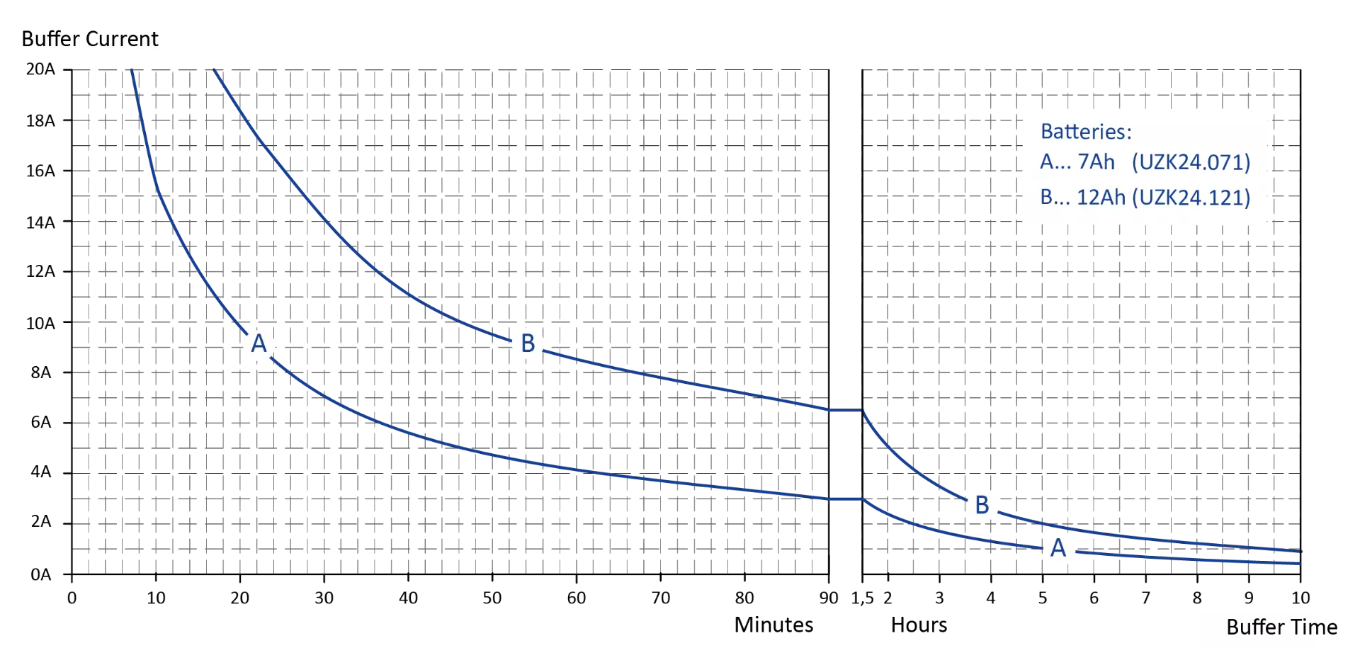
Graph 2: Hold-up time depending on the buffer current of a battery
Fundamental differences in terms of lifetime and resistance to temperatures
Lifetime
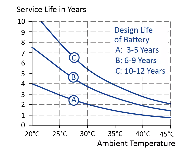
In ideal conditions and at an ambient temperature of 20 °C, lead-acid batteries often have a long but limited life. According to Eurobat, a lead-acid battery has a lifetime of 6 – 9 years. Few but relevant factors can affect the lifetime of a lead-acid battery. Pre-aging, which occurs during storage, must also be taken into account. Temperature, however, has the greatest impact on reducing the lifetime of lead-acid batteries. For example, an increase of 10 °C can halve the specified lifetime value (see graph 3).
The capacitors are permanently built into the device, cannot be replaced and – if the design is correct – have the same lifetime as the power supply itself. Typically, the lifetime of a power supply is more than 10 years in a typical application. Therefore, electrochemical double-layer capacitors are generally maintenance-free. Electrochemical double-layer capacitors have a nearly unlimited storage time and they do not need to be recharged regularly. Additionally, putting a system into operation later than anticipated or not using it for a longer period of time does not lead to any unwanted surprises.
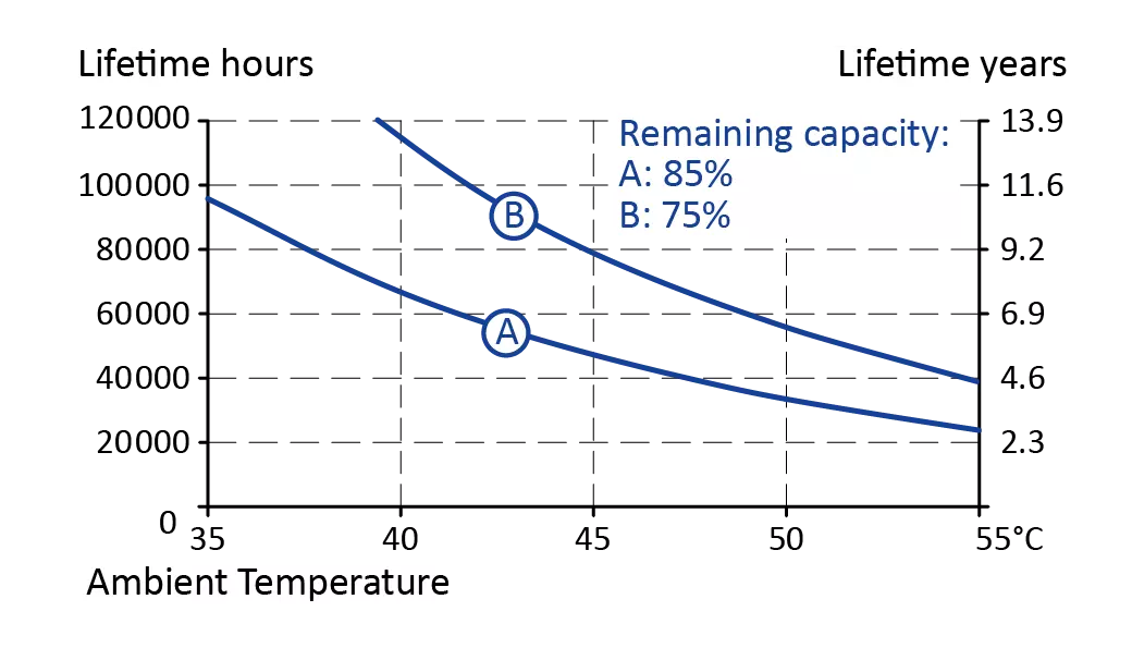
Similar to the batteries, the temperature also has an influence on the lifetime of capacitors: At an increase of 10 °C, the lifetime of the capacitors is halved (see graph 4) because the warmer it is, the faster the electrolytic capacitors will dry out.
Temperature
Lead batteries are sensitive to temperatures that are too low or too high. During charging, the hydrogen can freeze at temperatures below -10 °C, which is harmful to the battery. For such cold applications, pure lead batteries can be used instead. Since lead batteries leak hydrogen in temparatures above +45 °C, it is recommended that lead batteries be mounted outside the control cabinet.
Electrochemical double-layer capacitors are resistant to cold temperatures and can withstand temperatures as low as -40 °C. This makes these components ideal for outdoor, mobile or solar and wind power applications. Electrochemical double-layer capacitors provide full performance even up to +60 °C, which makes them suitable for use inside a closed and unventilated control cabinet.
Unlike lead-acid batteries, capacitors do not emit hydrogen and there is no need to vent the switch cabinet, as required by EN 50272-2 for lead-acid batteries.
How to calculate the energy content of batteries and capacitors?
The nominal capacity of a battery is given in Ah (ampere-hours). Together with the voltage, this gives us the approximate energy content:
Energy (Wh) = Voltage (V) * Capacity (Ah)
Caution with the different measurements units – kWs or kJ:
The capacitor voltage decreases continuously during discharge. Specifying the energy in Ah (ampere hours), as is normal for batteries, makes no sense, so the energy is specified in Wh (watt hours) or in kWs (kilo watt seconds). Often, one also finds the indication kJ (kilo Joule). 1 kJ corresponds to exactly 1 kWs. A value of 1kWs means that 1 kW of energy can be extracted for one second or 100 W corresponding to 10 seconds. The energy in a capacitor is calculated by the following formula:
Energy (Ws) = ½ CU2
This describes the energy when the capacitor is completely discharged to zero volts. However, in practice, converters cannot operate to zero volts, so it is not possible to use up the full energy. Caution should therefore be taken here. Buffer modules are classified by rated energy, not usable energy. When determining the hold-up time, always use the data sheet values or diagrams and not the simple approach shown above.
Summary
Which UPS system is suitable for which application?
The answer to the question of which UPS system is suitable for which application cannot be generalized. Each application is individual and, therefore, requires an individual analysis. This is the only way to ensure an uninterruptible power supply. However, there are certain questions that can help to find the ideal backup application for your system:
- What output voltage is required?
- How much power must be available as a backup?
- How much backup time is required?
- And finally, are there any loads in this application that do not require backup, and if so, how many?
This information can be used to prepare recommendations for the required output power of the power supply, as well as for the backup method and any additional equipment that may be required.
UPS modules with batteries are suitable for applications that require a long buffer time in case of emergency:
The UPS modules of the PULS UB series are often used in systems that must bridge a long gap until a service technician can fix the problem. This includes signal lights on radio masts or wind turbines, for example.
UPS modules with capacitors provide a short buffer time:
In regions with poor grids, PULS UF modules can bridge the failure of individual half-waves. However, they can also be used to supply an application that typically runs at 3 A but sometimes also runs at 12 A for short periods of time.
In the event of a power failure, the modules of the PULS UC series ensure that a system is switched off and shut down safely, including data backup. Additionally, machine arms or axes can be moved to a safe position.
The PULS tip
PULS offers two buffer modules with different storage sizes: the UC10.241 with a 6kWs storage and the UC10.242 with 12 kWs storage.
The units are designed for 24 V systems and can be loaded with up to 15 A in normal and buffer mode. Both units have a capacitor storage with built-in control electronics inside a compact, DIN rail mountable housing. The series connection of the individual capacitors is equipped with an active “balancer circuit”, which benefits a long lifetime. For monitoring and diagnosis, the unit is equipped with signal contacts and display elements. If buffering is not desired, this can be inhibited with the inhibit input.
For the application of DC-UPS modules with batteries, we offer two solutions using different devices:
The PULS device UB20.241 with the battery UZK24.121 keeps the output voltage stable at the set value of the buffer voltage in case of buffering. Values from 22.5 V to 26 V can be set, regardless of the battery voltage. In contrast, the UB40.241 device with the UZK24.262 battery directly passes on the battery voltage at the output, minus a small voltage drop.

