What is AC Inrush Current? How can it be limited?
A high inrush current is problematic for an efficient and simplified system design. Therefore power supply manufacturers try to keep AC inrush as low as possible. In this blog article you will learn why inrush current occurs in power supplies and which methods manufacturers apply to minimize it.
Probably most of us already have noticed the effect of an AC inrush current in our homes – e.g. when the refrigerator, power tools, vacuum cleaner or the air conditioner turn on. The surrounding lights may dim shortly, a sign that the AC voltage is being drawn down by the switch-on process of this device.
Fortunately, in the home environment, flickering lights are typically the worst condition that occurs. However, in an industrial environment, inrush current has potential risks. It can have a negative impact on operating systems, with unexpected down time or even damage to expensive equipment.
In addition, when selecting other system components such as circuit breakers, switches, relays, etc., the inrush current must always be taken into account. This means the lower the inrush current, the lower the additional effort in terms of system design and maintenance.
But first, let’s define what exactly AC inrush current is and why it occurs.
What is AC inrush current for a power supply?
In short, the inrush current is the power surge at the input of a power supply. It occurs during a short time period, when the input capacitors charge up after the input voltage is applied. The inrush current is higher than the nominal or operational current of the power supply.
Therefore, it needs to be limited to ensure a stable operation and to avoid tripping fuses or circuit breakers. There are various technological solutions to achieve a low inrush current.
How can AC inrush current be limited?
In the following, we will explain the four most common methods, that are used to limit the inrush current in industrial power supplies.
1. Inrush current limitation using NTC thermistors
NTC is short for “Negative Temperature Coefficient”. NTC thermistors are the easiest and the least expensive way of limiting the inrush current. This solution is based on thermally sensitive semiconductor resistors which show a decrease in resistance as temperature increases.
When power is first applied, the NTC thermistor is cold, so it has a high impedance and effectively limits the charging current to the input capacitors. The NTC thermistor heats up very rapidly due to its own losses, so the impedance drops to a low level, allowing all the required current to flow.
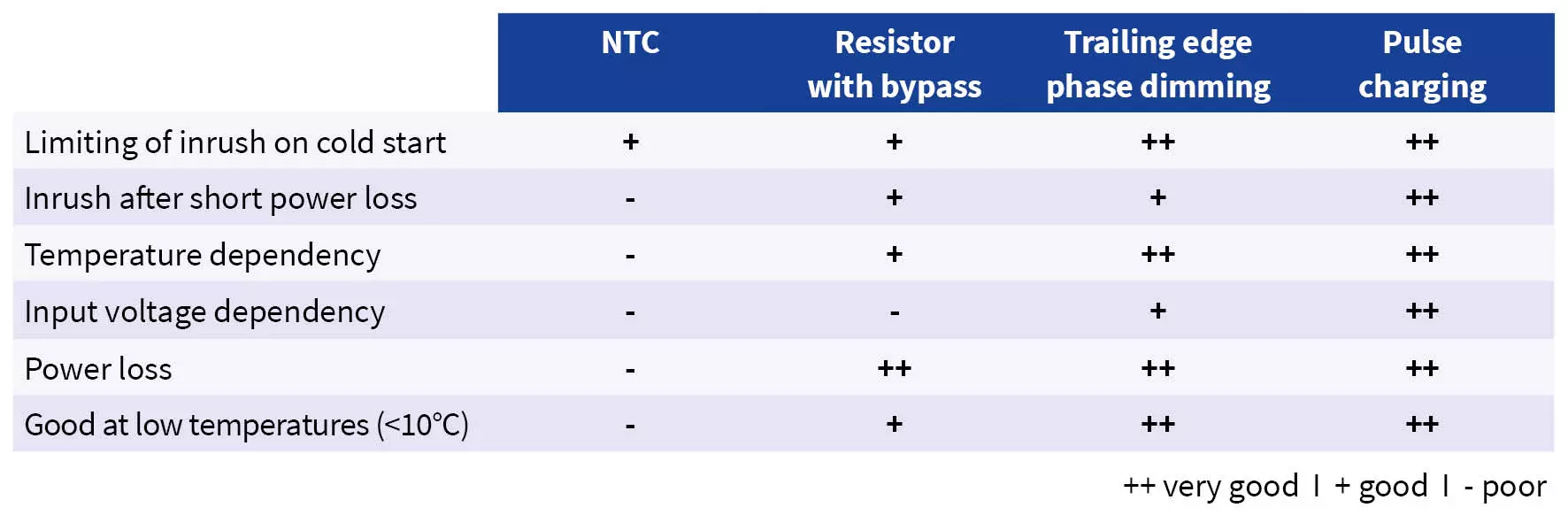
This solution also has some disadvantages. The effect of temperature sensitive resistors on the inrush current strongly depends on the ambient temperature.
If it is too cold (e.g. below zero °C), start-up problems can occur. If it is too hot, the inrush current limitation of the NTC thermistors may not work correctly.
Another disadvantage of NTC thermistors is the inadequate inrush current limitation following short AC voltage interruptions: As soon as the AC voltage is interrupted the electrolytic capacitors are discharged. But the NTC thermistor remains at low impedance because it is already heated up. Therefore, the thermistor is practically ineffective when the AC is restored. This effect can damage the capacitors.
NTC thermistors also generate power losses due to its functionality. This can lower the overall efficiency of the power supply.
2. Inrush current limitation using fixed resistors
The inrush current can also be limited with a fixed power resistor. After the electrolytic capacitors on the input of the power supply are charged, the resistor is bypassed.
There are several different components that can be used to bypass the resistor such as relays, triacs or IGBTs.
This method of inrush current limitation is significantly more complex and expensive than the usage of NTC thermistors. Therefore, it is primarily used in power supplies with larger wattage designs (250W and above). The advantages are that fixed resistors work independently from the ambient temperature and cause significantly less power losses.
3. Inrush current limitation using trailing edge phase dimming
Trailing edge phase dimming works similar to the solution with fixed resistors. The limiting path is bridged with a relay after charging the capacitors. What makes this solution special is the limiting part itself.
An electronic system measures the instantaneous value of the AC voltage and compares it with the voltage of the partly charged capacitors. If the difference is less than a set threshold of e.g. 30 V, a MOSFET closes. If the difference is bigger than 30 V, the MOSFET reopens.
The on-resistance of the MOSFET thereby limits the peak charging current. For example, if the on-resistance has a value of 4 ohms, the current is limited to 7.5 A (30 V /4 ohms). A gentle start for all input voltages is therefore guaranteed. If the input capacitor is fully charged the inrush current limiting circuit is bridged to avoid power losses.
PULS uses this technique in many of its DIMENSION C series devices.
4. Inrush current limitation using pulse charging of the input capacitor
Pulse charging is a smart and efficient way of softly controlling how much energy is allowed to charge the input capacitor. To achieve this, a little switched-mode power supply is integrated and used as a charging circuit. This enables a very efficient charging of the input capacitor with no losses.
This method leads to a couple of advantages:
- The inrush current is only slightly higher than the normal operating current.
- The peak current can be defined more accurately, as there are no variables involved.
- A delay on the charging is also incorporated into the design. This means when power is initiated or restored, the supply does not contribute to unnecessary inrush as neighboring equipment is also energized.
- Fuses or circuit breakers can be sized for operating current and not peak current.
- The inrush current limitation is independent of input voltage or temperature
The pulse charging is highly efficient and is used in many DIN rail power supplies of PULS DIMENSION Q series.
Summary
There are various options to limit the AC inrush current to a point where it is nearly on the same level as the operational current. Each method has its benefits and disadvantages, like temperature sensitivity or a higher price point. Which one is the right for you depends on your application and in which environment it is used. You can also consult our team of skilled application engineers to find the best solution.


